Formula
LCR series circuit impedance
Z = √(R² + (X_L - X_C)²). Phase angle: tan φ = (X_L - X_C)/R. Current I = V/Z lags or leads V depending on sign of (X_L - X_C).
-- NCERT Class 12 Physics, Ch. 7, p. 188The common failure in a series LCR question is not the concept — it is the arithmetic chain. A typical item asks for impedance, then current, then a component voltage, and every line offers a chance to add the reactances instead of subtracting them, or to lose a factor. The distractors are built from exactly those slips, so a mis-step lands on an option rather than on nothing. Work one substitution per line, and sanity-check each result before feeding it into the next.
The circuit itself is simple. R, L and C carry the same current, so current is the reference phasor. The voltage across R is in phase with it, the voltage across L leads it by 90°, the voltage across C lags it by 90°. V_L and V_C therefore point in opposite directions and partly cancel. Adding the three as phasors gives the result in NCERT Class 12 Physics, Chapter 7, page 188:
Z = √(R² + (X_L − X_C)²), tan φ = (X_L − X_C)/R
Two things follow. Z is never smaller than R — the reactive part can only add under the square root. And the sign of (X_L − X_C) fixes the circuit's character: positive means inductive, current lagging; negative means capacitive, current leading; zero is the resonance case, which has its own lesson.
The consequence students reject on first sight: the RMS voltage across L alone can exceed the source RMS voltage. Nothing is violated. Only the phasor sum must return the source voltage, and the antiphase V_C cancels most of V_L. A voltmeter reading three times the source voltage across an inductor is ordinary.
In NEET this topic carries roughly 0.4 questions a year, usually impedance or phase angle from given R, X_L and X_C, sometimes component voltages read off a phasor description. Negative-marking risk is medium.
Watch-out: subtract the reactances before squaring, never after — and confirm Z ≥ R before you divide by it.
Select an option to see the explanation. Wrong answers show why your choice was tempting — and name the exact trap it exploits.
In a series LCR circuit driven by an AC source, which quantity has the same instantaneous value in the resistor, the inductor and the capacitor?
Answer: B. The three elements are in series, so the same current passes through each at every instant; this is why current is taken as the reference phasor in the impedance construction of NCERT Class 12 Physics, Chapter 7, page 188.
Why A is wrong: A is wrong because the three element voltages differ in both magnitude and phase — that difference is precisely what the phasor triangle encodes.
Why C is wrong: C is wrong because the ideal inductor and capacitor dissipate no average power at all, while the resistor does; the values are not equal.
Why D is wrong: D is wrong because the resistor voltage is in phase with the current, the inductor voltage leads it by 90°, and the capacitor voltage lags it by 90° — three different phase relationships.
In a series LCR circuit, the phasor representing the voltage across the inductor and the phasor representing the voltage across the capacitor are
Answer: C. V_L leads the common current by 90° and V_C lags it by 90°, so the two are 180° apart — antiphase. That is the reason the reactances enter the impedance as a difference, as set out in NCERT Class 12 Physics, Chapter 7, page 188.
Why A is wrong: A is wrong because if V_L and V_C were in phase they would reinforce, and the impedance would contain (X_L + X_C) rather than (X_L − X_C).
Why B is wrong: B is wrong because 90° is the angle each of them makes with the current (and with V_R), not the angle between them.
Why D is wrong: D is wrong because 45° is a phase angle that arises for the whole circuit when |X_L − X_C| happens to equal R; it is not a fixed relationship between V_L and V_C.
For a series LCR circuit, the phase angle φ between the source voltage and the current is given by
Answer: D. In the impedance triangle the reactive side is (X_L − X_C) and the resistive side is R, so tan φ is their ratio, as stated alongside the impedance relation in NCERT Class 12 Physics, Chapter 7, page 188.
Why A is wrong: A is wrong because it inverts the triangle — R/(X_L − X_C) is cot φ, and using it makes an inductive circuit look capacitive in magnitude of angle.
Why B is wrong: B is wrong on two counts: the reactances are subtracted, not added, and the ratio of the reactive side to R is a tangent, not a sine.
Why C is wrong: C is wrong because (X_L − X_C)/Z is sin φ; cos φ is R/Z, the resistive side over the hypotenuse.
A series LCR circuit has R = 3.0 × 10¹ Ω, X_L = 8.0 × 10¹ Ω and X_C = 4.0 × 10¹ Ω at the operating frequency. The impedance of the circuit is
Answer: A. X_L − X_C = 4.0 × 10¹ Ω, so Z = √((3.0 × 10¹)² + (4.0 × 10¹)²) = 5.0 × 10¹ Ω, using the series impedance relation of NCERT Class 12 Physics, Chapter 7, page 188.
Why B is wrong: B is wrong because it adds all three quantities as ordinary numbers (30 + 80 + 40). R, X_L and X_C are phasor components at different angles and cannot be summed arithmetically.
Why C is wrong: C is wrong because it adds the reactances instead of subtracting them: √(30² + 120²) ≈ 1.2 × 10² Ω. V_L and V_C are antiphase, so the reactances cancel in part.
Why D is wrong: D is wrong because it reports only the net reactance (X_L − X_C) and drops R entirely; Z can never be less than R.
A series LCR circuit has R = 1.5 × 10¹ Ω, X_L = 2.5 × 10¹ Ω and X_C = 4.0 × 10¹ Ω. The phase angle between the source voltage and the current, and the nature of the circuit, are
Answer: D. X_L − X_C = −1.5 × 10¹ Ω, so tan φ = −15/15 = −1, giving φ = 45° with the negative sign marking a capacitive circuit in which the current leads — the sign convention of NCERT Class 12 Physics, Chapter 7, page 188.
Why A is wrong: A has the right magnitude but the wrong sense: X_C exceeds X_L here, so the circuit is capacitive and the current leads, it does not lag.
Why B is wrong: B is wrong because tan φ = 1 gives 45°, not 60°; 60° would require |X_L − X_C| = √3 R.
Why C is wrong: C is wrong because X_L and X_C are unequal, so the net reactance is non-zero and the circuit is not purely resistive.
In a series LCR circuit the RMS voltages measured across the individual elements are V_R = 4.0 × 10¹ V, V_L = 1.0 × 10² V and V_C = 7.0 × 10¹ V. The RMS voltage of the source is
Answer: A. The element voltages add as phasors: V = √(V_R² + (V_L − V_C)²) = √(40² + 30²) = 5.0 × 10¹ V, the voltage form of the impedance triangle in NCERT Class 12 Physics, Chapter 7, page 188.
Why B is wrong: B is wrong because it adds the three readings arithmetically (40 + 100 + 70). Voltages at different phases never add that way in an AC circuit.
Why C is wrong: C is wrong because it adds V_L and V_C instead of subtracting: √(40² + 170²) ≈ 1.7 × 10² V. The two are antiphase and partly cancel.
Why D is wrong: D is wrong because it keeps only V_R and ignores the net reactive voltage, which here is a non-zero 3.0 × 10¹ V.
In a series LCR circuit, the RMS voltage measured across the inductor alone is found to be larger than the RMS voltage of the source. This observation is
Answer: C. Only the phasor sum √(V_R² + (V_L − V_C)²) must equal the source voltage; a large V_L can be offset by a large V_C pointing the opposite way, so V_L alone may exceed the supply — a direct reading of the construction in NCERT Class 12 Physics, Chapter 7, page 188.
Why A is wrong: A is wrong because an ideal inductor stores and returns energy each cycle rather than dissipating it; a large reactive voltage creates no net energy.
Why B is wrong: B is wrong because that arithmetic-sum rule holds for DC series circuits, not for AC, where the element voltages differ in phase.
Why D is wrong: D is wrong because the effect needs only a substantial X_C to oppose V_L; it occurs at ordinary non-zero R, and R = 0 is not a condition for it.
A series LCR circuit is connected to a source of RMS voltage 2.0 × 10² V. At the operating frequency R = 6.0 × 10¹ Ω, X_L = 1.0 × 10² Ω and X_C = 2.0 × 10¹ Ω. The RMS voltage across the resistor is
Answer: B. X_L − X_C = 8.0 × 10¹ Ω, so Z = √(60² + 80²) = 1.0 × 10² Ω, giving I = 200/100 = 2.0 A and V_R = IR = 1.2 × 10² V, following the impedance relation of NCERT Class 12 Physics, Chapter 7, page 188.
Why A is wrong: A is wrong because it assumes the whole source voltage appears across R; that holds only when the net reactance is zero, and here it is 8.0 × 10¹ Ω.
Why C is wrong: C is wrong because it adds the reactances instead of subtracting, giving Z ≈ 1.34 × 10² Ω and I ≈ 1.5 A. The antiphase V_C reduces the net reactance rather than increasing it.
Why D is wrong: D is wrong because it drops R from the impedance (Z = 80 Ω, I = 2.5 A) while still multiplying by R at the end — R must appear in both places.
Get a structured 30-day Mechanics plan and a complete formula booklet — delivered to your inbox instantly.
Given.
A series LCR circuit across a sinusoidal source of RMS voltage 1.0 × 10² V. At the operating frequency: R = 3.0 × 10¹ Ω, X_L = 7.0 × 10¹ Ω, X_C = 3.0 × 10¹ Ω.
Required.
The impedance, the RMS current, and the phase angle between source voltage and current, with the nature of the circuit stated.
Concept.
The three elements share one current, so current is the reference phasor. V_R is along it, V_L leads by 90°, V_C lags by 90°. The two reactive voltages are antiphase, so the net reactive side of the impedance triangle is (X_L − X_C) and the resistive side is R.
Formula.
Z = √(R² + (X_L − X_C)²); I = V/Z; tan φ = (X_L − X_C)/R.
Substitution.
X_L − X_C = 7.0 × 10¹ − 3.0 × 10¹ = 4.0 × 10¹ Ω
Z = √((3.0 × 10¹)² + (4.0 × 10¹)²)
Calculation.
Z = √(9.0 × 10² + 1.6 × 10³) = √(2.5 × 10³) = 5.0 × 10¹ Ω
I = (1.0 × 10²)/(5.0 × 10¹) = 2.0 A
tan φ = (4.0 × 10¹)/(3.0 × 10¹) = 1.33 → φ = 53°
Final answer.
Z = 5.0 × 10¹ Ω, I = 2.0 A, φ = 53° with the current lagging the source voltage — an inductive circuit. The exponent 2 in the squares and the square-root operation are exact mathematical operations and contribute nothing to the significant-figure count; the answers carry two significant figures, inherited from the two-significant-figure data.
Common trap.
The cascade. Three chained lines (net reactance → Z → I, then φ) each invite a slip, and the option list is stocked with the results: adding the reactances gives Z ≈ 1.04 × 10² Ω and I ≈ 0.96 A; dropping R gives Z = 4.0 × 10¹ Ω and I = 2.5 A; inverting the tangent ratio gives φ = 37°. Do the subtraction on its own line before squaring, then verify Z ≥ R — here 50 Ω ≥ 30 Ω — before dividing. Note also that if X_L and X_C had been equal, Z would collapse to R; that limiting case is the resonance lesson's subject, not this one.
Similar NEET-style question.
A series LCR circuit is fed by a source of RMS voltage 2.0 × 10² V. At the operating frequency R = 8.0 × 10¹ Ω, X_L = 4.0 × 10¹ Ω and X_C = 1.0 × 10² Ω. Find the impedance, the RMS current, and state whether the current leads or lags. *(Answer: Z = 1.0 × 10² Ω, I = 2.0 A, current leads — capacitive, φ = 37°.)*
Z = √(R² + (X_L - X_C)²). Phase angle: tan φ = (X_L - X_C)/R. Current I = V/Z lags or leads V depending on sign of (X_L - X_C).
-- NCERT Class 12 Physics, Ch. 7, p. 188Effective resistance of series LCR. Phase angle phi between V and I.
| Symbol | Quantity | SI Unit |
|---|---|---|
| Z | impedance | Ω |
| R | resistance | Ω |
| X_L, X_C | reactances | Ω |
| phi | phase angle | rad |
These are the exact patterns that cause wrong answers in NEET. Each trap includes when it triggers and how to avoid it.
Category: Negative Marking
Multi-step LCR resonance problem (compute resonance frequency, then current, then impedance). Each sub-step has factor-of-2π or sqrt-of-2 error opportunities. Final answer can be off by 4× cumulatively.
LCR question asks for current/voltage/power at resonance with multi-step computation.
Slow down. Compute f_0 = 1/(2π√(LC)) carefully. Then ω_0 = 2πf_0. Then Z = R, I = V/R. Each line one substitution; check unit/order at each step. Answers off by powers of 2π or √2 are deliberate distractors.
More in Electromagnetic Induction and Alternating Currents: 3 exam traps and mistakes · 10 formulas · 5 question patterns from its other lessons.
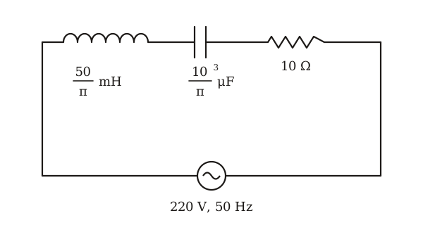
The net impedance of circuit (as shown in figure) will be
All 20 past-paper questions from Electromagnetic Induction and Alternating Currents →
forgets square root
Uses 1/(2π LC) without sqrt
conflates X_L X_C formulas
Substitutes wrong reactance formula
Page numbers are the ones printed in the current NCERT textbook (2023 rationalised edition), unless marked pre-2023. The books are free at ncert.nic.in.
Test yourself on this topic with real past-paper questions:
Practice this topic →